Sign In | Join Free | My himfr.com |
|
Ask Lasest Price | |
Brand Name : | Sinuo |
Model Number : | SN4420 |
Certification : | Calibration Certificate (Cost Additional) |
Price : | Negotiable |
Payment Terms : | T/T |
Supply Ability : | 30 Sets Per Month |
Delivery Time : | 30 Days |
UL154B Water Spray Test Apparatus With 3 UL Spray Heads Manual
Version
Product Information:
The testing equipment is used to verify the protective performance
of the enclosure for self-ballasted lamps and lamp adapters under
UL water spray environment.
The water ingress testing equipment apply spray test to test sample
by controlling the water supply pressure and the distance between
the nozzle and sample.
Standards Compliant:
UL1993 “Self-Ballasted Lamps and Lamp Adapters” clause 24, figure
24.1 and 24.2
UL60507-ENGL 1999 figure 38.1 and 38.2
ANSI Z21.10.3-2004
ANSI Z21.58 Figure 10/Figure 11
CSA4.3-2004
UL1598, UL153, UL154B, UL1703, UL8750, UL1741, UL514B, UL1278,
UL1571, etc.
Features:
A water spray test apparatus, also known as a water spray test
chamber or water spray nozzle system, is a specialized equipment
used to assess the resistance of electronic devices, enclosures, or
materials to water spray or jetting. This type of testing is often
conducted to evaluate the ingress protection (IP) rating of the
test specimen according to standards like the International
Electrotechnical Commission (IEC) 60529 or the National Electrical
Manufacturers Association (NEMA) standards. Here are the key
features and functions typically associated with a water spray test
apparatus:
Test Chamber: The apparatus consists of a testing chamber or
enclosure where the test specimen is placed. The chamber is
designed to contain the water spray or jetting and prevent water
from escaping outside the testing area.
Water Supply System: The apparatus incorporates a water supply
system that provides a controlled and pressurized water source.
This system typically includes pumps, valves, and filters to
maintain a consistent and specified water pressure and flow rate
during the test.
Spray Nozzles: The apparatus features spray nozzles or jets
strategically positioned within the test chamber. These nozzles
generate a directed water spray or jetting pattern onto the test
specimen. The number, size, and arrangement of the nozzles may vary
depending on the specific testing requirements and standards being
followed.
Water Pressure and Flow Control: The apparatus allows precise
control over the water pressure and flow rate during the test. This
control ensures that the water spray or jetting meets the required
specifications outlined in the testing standards.
Angle Adjustment: Some water spray test apparatuses offer the
ability to adjust the angle of the spray nozzles. This feature
allows for testing at different angles to simulate real-world
scenarios where the test specimen may be exposed to water from
various directions.
Test Duration Control: The apparatus provides control over the
duration of the water spray or jetting test. The test duration is
typically specified in the relevant standards, and the apparatus
allows for precise timing and automation of the test process.
Compliance with Standards: A water spray test apparatus is designed
to comply with specific industry standards such as IEC 60529 or
NEMA standards. Compliance ensures that the testing process is
conducted according to established guidelines and provides reliable
and comparable results.
Water spray test apparatuses are commonly used in industries such
as automotive, aerospace, electronics, and outdoor equipment
manufacturing. They enable manufacturers to evaluate the waterproof
or water-resistant properties of their products, ensuring they meet
the required IP ratings and can withstand exposure to water spray
or jetting without compromising functionality or safety.
Technical Parameters:
Control & Operation | Manual |
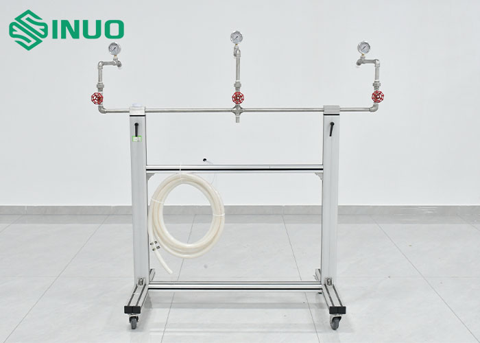
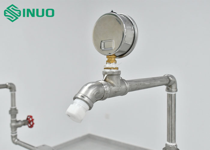
Spray Heads | 3 pieces (or 4 pieces optional, with one lower nozzle), manufactured according to UL1993figure 24.1 |
Spray Heads Positions | The positions of spray heads can be adjusted up or down through the water spray pipe rack, the spacing is made according to UL1993 Figure 24.2 |
Lower Nozzle Angle (Optional) | 45° up |
Water Pressure | At each head at approximately 34.5Kpa (5 psi), each spray head has a corresponding press gauge, total water flow pressure is 50-150Kpa |
Distance between the center Nozzle and the Device | Approximately 1.4m (55 inches) |
Rack | Material: high-grade aluminum profile with casters |
The device consists of a 3 UL spray heads, 3 pressure gauges, 3
control valves and a water supply pipe rack.
Note: we only quote the test apparatus, the water supply should be
offered by client.
![]() |